
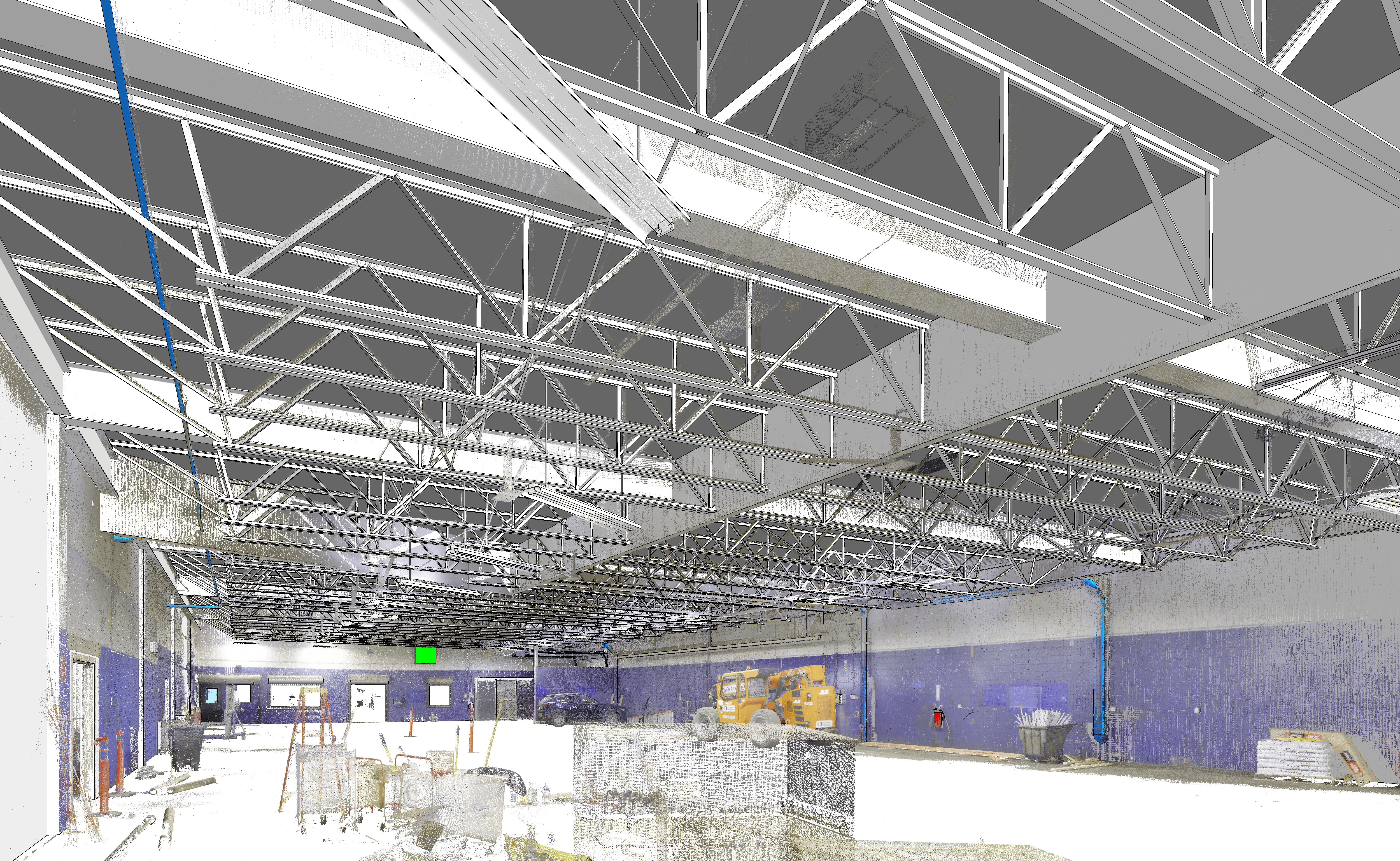

Turning a point cloud into a Revit model sounds straightforward.
Scan the building. Register the data. Build the model. Deliver the RVT file.
In practice, the decisions made before modeling begins often matter as much as the scan itself.
What needs to be modeled? At what level of detail? Which systems matter to the project? What coordinate system does the design team need? Should existing irregularities be represented exactly, or should the model use standard Revit geometry where appropriate?
A point cloud captures measured reality.
A Revit model organizes that reality into building elements a project team can design, coordinate, document, and plan around.
Getting from one to the other requires more than tracing geometry.
It requires defining what the model needs to do.
Table of Contents
What Is a Point Cloud?
A point cloud is a dense collection of measured points captured from the physical environment.
3D laser scanners collect millions of measurements across visible surfaces, producing a three-dimensional record of the scanned space.
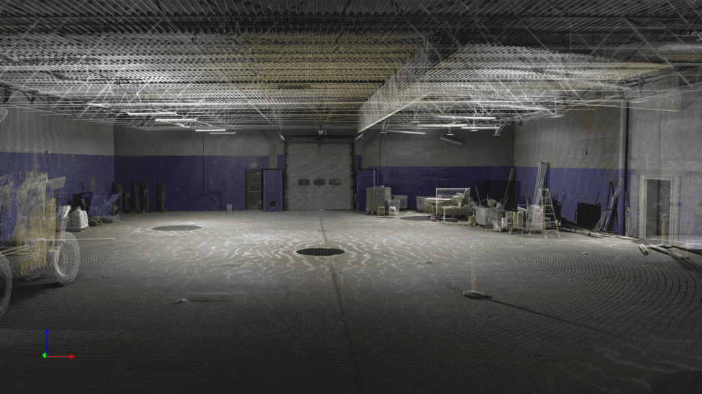
Depending on the scope, that dataset can capture:
- walls and floors
- structural members
- ceiling conditions
- ductwork
- piping
- electrical systems
- equipment
- penetrations
- openings
- clearances
- other visible geometry
The point cloud is valuable because it preserves measured field conditions at the time of capture.
But it is not the same thing as a BIM model.
A point cloud does not inherently know that a group of points represents a wall, pipe, beam, or piece of equipment.
That interpretation happens during the Scan-to-BIM process.
What Does “Point Cloud to Revit” Actually Mean?
Point cloud to Revit is the process of using registered reality capture data as the reference for creating an organized Revit model of existing conditions.
The point cloud provides the measured geometry.
The modeler uses that geometry to build Revit elements that correspond to the physical environment.
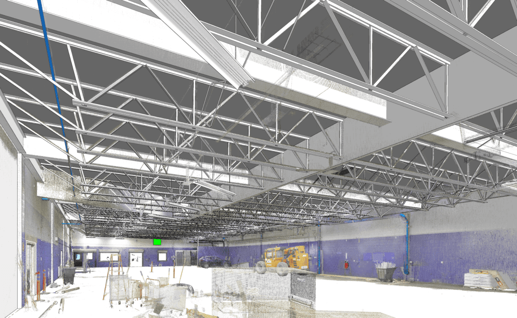
Depending on the project, those elements might include:
- architectural walls, floors, ceilings, doors, and openings
- structural columns, framing, slabs, and foundations
- mechanical ductwork and equipment
- plumbing and piping
- electrical elements
- fire protection systems
- selected equipment or infrastructure
The result is not simply a smaller or cleaner version of the point cloud.
It is a structured model designed for downstream use.
That distinction matters because two Revit models built from the same scan can be very different depending on what the project requires.
A Point Cloud and a Revit Model Serve Different Jobs
The point cloud is the measurement record.
The Revit model is an interpretation of that record for a specific workflow.
That means one is not automatically “better” than the other.
A design team may want both.
The point cloud allows someone to return to the captured field data and inspect geometry directly.
The Revit model makes that geometry easier to use for tasks such as:
- renovation design
- BIM coordination
- clash detection
- equipment planning
- MEP routing
- drawing production
- spatial planning
- retrofit design
- construction documentation
A good Scan-to-BIM delivery preserves the connection between the two.
The model should be built against the captured conditions, while the point cloud remains available as the underlying reference when questions arise.
The Most Important Decision Comes Before Modeling
One of the most common mistakes in Scan-to-BIM scoping is asking for “a Revit model” without defining what that means.
Revit is the file format and modeling environment.
It does not define the scope.
Before modeling begins, the project team should establish:
- which areas are included
- which disciplines need to be modeled
- the required level of detail
- which elements matter most to the project
- coordinate requirements
- required file structure
- how the model will be used downstream
Consider a mechanical retrofit.
The engineering team may need highly useful information about ductwork, piping, equipment, structure, and available clearances.
It may not need every architectural finish or piece of furniture modeled to the same level.
A facility documentation project might require a different balance.
A structural renovation will have different priorities again.
The Scan-to-BIM scope should follow the project need, not a generic modeling template.
How the Point Cloud to Revit Workflow Works
A typical workflow can be organized into five stages.
1. Define the Deliverable
Before anyone scans the site, determine what the final model needs to support.
Questions should include:
- What is the project trying to design or coordinate?
- Which systems need to appear in Revit?
- How much of the facility needs to be captured?
- What level of detail is appropriate?
- How will the model be coordinated with other project files?
- Does the team need the point cloud in addition to the Revit model?
Defining these requirements early helps align the field scope and modeling effort with the actual project.
2. Capture the Existing Conditions
The field team captures the required spaces using the reality capture method appropriate to the site and project requirements.
The objective is not simply to collect as much data as possible.
It is to capture the geometry needed to support the agreed deliverable.
Access, line of sight, obstructions, occupied areas, safety requirements, and operating conditions all affect field planning.
For industrial and retrofit projects, understanding the downstream modeling need before mobilization is particularly useful because the critical geometry may be above ceilings, behind equipment, or within congested mechanical areas.
3. Register and Prepare the Point Cloud
Individual scan positions are combined into a coordinated dataset.
The point cloud is then prepared and reviewed according to the project requirements before modeling begins.
At this stage, the team should also confirm that the dataset covers the areas and systems included in the modeling scope.
Finding a coverage gap after modeling has started is much more disruptive than identifying it during processing and QA.
4. Build the Revit Model
The modeler uses the registered point cloud as the geometric reference for creating the agreed Revit elements.
This is where project-specific judgment becomes important.
Existing buildings are rarely perfect.
Walls may not be perfectly straight.
Floors may vary.
Structural elements may not sit exactly where old drawings indicate.
Piping and ductwork may have been modified many times.
The model needs to represent the captured condition at the level appropriate to the project’s use case without adding unnecessary complexity.
That is why scope and modeling expectations need to be agreed before this stage begins.
5. QA the Model Against the Source Data
The finished Revit model should be reviewed against the point cloud used to create it.
This is different from field registration QA.
The question now is whether the modeled elements appropriately represent the captured geometry and agreed scope.
QA may include reviewing:
- model completeness
- critical geometry
- element placement
- modeled systems
- project coordinates
- scope requirements
- areas where simplified Revit geometry differs from irregular real-world conditions
The goal is not to make the digital model artificially perfect.
It is to ensure that the model is fit for the decisions it was created to support.
How Much Detail Should a Scan-to-BIM Model Include?
More detail is not automatically more useful.
Every additional modeled element requires time to create, review, manage, and maintain.
The right question is:
What information does the project team actually need from this model?
For example, a project coordinating mechanical equipment installation may care heavily about:
- structural framing
- existing MEP routing
- equipment
- penetrations
- access
- clearances
The same project may gain little value from detailed modeling of decorative architectural finishes.
This is why LOD should not be treated simply as a number selected from a proposal template.
The modeling scope should identify what needs to be represented and why.
A narrower model with the right information can be more useful than a highly detailed model filled with elements that do not support the project.
Should Existing Irregularities Be Modeled Exactly?
This is another question worth answering during scoping.
The physical world and Revit do not behave the same way.
Real buildings contain:
- slightly out-of-plumb walls
- deflected framing
- irregular surfaces
- field-routed systems
- nonstandard equipment
- imperfect intersections
Revit is built around structured, parametric elements.
That means the project team needs to decide how closely unusual field geometry should be represented.
For some applications, representing an irregularity matters because installation clearance depends on it.
For others, standard geometry may be sufficient.
There is no universal answer.
The correct approach depends on what the model will be used to decide.
Do You Need the Point Cloud After the Revit Model Is Delivered?
Often, yes.
The Revit model makes existing conditions easier to incorporate into BIM workflows, but the point cloud remains the measured source.
Keeping both available gives teams another reference when questions arise.
For example, an engineer may later need to inspect an area that was scanned but was not included in the original modeling scope.
If the relevant condition is visible in the captured data, the point cloud may provide useful context without immediately requiring another site visit.
That does not mean scan data replaces every future field investigation.
Conditions can change after capture, and some elements may not have been visible or included in the scan.
But maintaining access to the source data increases the usefulness of the original reality capture effort.
Common Point Cloud to Revit Scoping Mistakes
Several problems can be reduced simply by defining expectations earlier.
Asking for a “full Revit model” without defining the scope
“Full” means different things to different teams.
Define disciplines, areas, elements, and project uses instead.
Choosing a level of detail without connecting it to the use case
LOD should support the downstream workflow.
Do not pay to model information the project does not need.
Failing to define coordinates early
If the Revit model needs to integrate with architectural, structural, civil, or trade models, coordinate requirements should be discussed before delivery.
Treating the model as the only useful output
The source point cloud can remain valuable throughout design and coordination.
Modeling before confirming field coverage
The modeling team cannot create reliable information for geometry that was never adequately captured.
The field and BIM scopes should be developed together.
What Should You Ask a Scan-to-BIM Provider?
Before commissioning a point cloud to Revit project, ask:
What do you need from us before scanning?
A good provider should want to understand your drawings, design scope, critical areas, coordinate requirements, and intended use.
How will the modeling scope be defined?
Look for a clear description of what will and will not be modeled.
How is the model checked against the point cloud?
The provider should have a defined QA process between the source data and the modeled deliverable.
What formats will we receive?
Confirm whether you need Revit, point cloud files, 2D documentation, or additional outputs.
Can the model integrate with our existing project environment?
Discuss Revit version, coordinate system, model structure, and other technical requirements early.
What happens if our scope changes later?
Understanding how the point cloud and model can support later phases helps avoid rebuilding work unnecessarily.
The Best Revit Model Starts With the End Use
Point cloud to Revit is not simply a file conversion.
The point cloud records what was captured in the field.
The Revit model turns selected parts of that measured information into a structure the project team can design, coordinate, and document from.
The quality of the final deliverable depends on more than scanning technology.
It depends on whether the field scope, modeling scope, level of detail, coordinate requirements, QA process, and downstream use were aligned from the beginning.
OAR provides 3D Laser Scanning and Scan-to-BIM services for engineering, construction, industrial, and facility teams that need existing-condition data delivered in a usable project format.
If you are planning a renovation, retrofit, coordination effort, or existing-facility project and need to determine whether your team needs a point cloud, Revit model, or both, we can help scope the right deliverable before mobilization.