
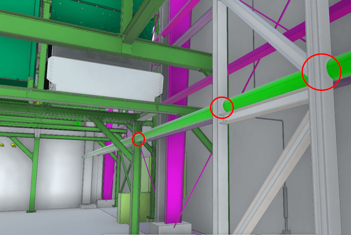
Industrial clash detection becomes more complex when new work has to fit inside an existing facility. The coordination team is not only checking one proposed system against another. Existing structure, piping, ductwork, conduit, equipment, supports, and previous modifications can all affect whether coordinated geometry will actually fit in the field.
That makes the quality of existing-condition information critical. A coordination model can appear clash-free and still conflict with the physical facility if relevant existing conditions are incomplete, outdated, or represented inaccurately.
For industrial retrofits, equipment installations, and facility upgrades, clash detection works best as part of a broader verification and coordination workflow: understand the existing environment, establish usable geometry, coordinate proposed work, and resolve spatial conflicts before installation.
What We’ll Cover
How Clash Detection Works With Existing Structures
Clash detection identifies spatial conflicts between geometry represented in a coordination environment. On a new construction project, teams may have relatively complete design and trade models for the systems being installed. Existing facilities introduce another variable: the physical environment may no longer match the available drawings or models.
Structural elements, piping, ductwork, conduit, equipment, supports, penetrations, and previous field modifications can all affect the space available for new work. Some conditions may be documented accurately. Others may have changed over years of operation, maintenance, repairs, and previous construction.
Clash detection can only evaluate geometry that is represented in the coordination environment. If a relevant existing condition is missing, the coordination process cannot identify a conflict with it.
Depending on the project, teams may use available record information, field verification, 3D Laser Scanning, point clouds, or Scan-to-BIM models to establish the existing conditions needed for coordination. The appropriate method depends on the project scope, required level of detail, available documentation, and downstream use.
Why Existing-Condition Data Changes the Quality of Clash Detection
The usefulness of clash detection depends on the information available for comparison.
In an existing industrial facility, coordination may need to account for both proposed systems and physical conditions already in place. When existing-condition information is incomplete, the federated model can provide an incomplete picture of the installation environment.
A stronger workflow connects field verification with BIM coordination:
Existing Facility → Field Verification → Existing-Condition Geometry → Proposed / Trade / Fabrication Models → Federated Coordination Model → Clash Review → Issue Resolution Before Installation
The objective is not to model every visible condition. The project team needs to identify which existing elements affect the coordination question and establish enough reliable information to support that use.
For example, a new mechanical installation may depend on the location of existing structure, overhead piping, ductwork, electrical systems, equipment, and available access space. Capturing and representing the relevant conditions gives the coordination team a better basis for evaluating how the proposed installation fits within the actual facility.
What Industrial Clash Detection Actually Reviews
Industrial clash detection can involve multiple types of geometry and multiple project participants.
A federated coordination model may bring together structural, mechanical, electrical, plumbing, fire protection, equipment, fabrication, and existing-condition information. The coordination team can then review where represented systems occupy the same space or where their arrangement creates another defined coordination issue.
Not every clash carries the same importance. Some may represent direct geometric conflicts. Others may relate to access, installation sequencing, maintenance space, or project-specific clearance requirements.
The purpose of the coordination process is therefore not simply to generate a large clash report. The project team needs a structured way to identify relevant issues, assign responsibility, evaluate proposed resolutions, and track those issues through the coordination cycle.
Where Conflicts Can Appear in Existing Industrial Facilities
Existing Structure
New piping, ductwork, conduit, equipment, and supports may need to fit around existing beams, columns, walls, slabs, and other structural elements.
When the existing structure differs from the information used for coordination, a proposed route that works in the model may not fit the physical space.
Existing MEP Systems
Industrial facilities often contain dense networks of piping, ductwork, conduit, cable trays, sprinkler systems, and other building services.
Existing systems can constrain routing options for new work, particularly in overhead spaces and areas where multiple trades share limited space.
Equipment and Supports
Equipment geometry, bases, supports, frames, platforms, and adjacent systems can affect both placement and routing.
For equipment suppliers and installation teams, coordination may also need to account for the relationship between the equipment geometry and the surrounding facility before fabrication or installation proceeds.
Penetrations and Connection Points
Existing openings, sleeves, connection points, and penetrations can influence where new systems can be routed or connected.
When these conditions are critical to the proposed work, verifying their location can provide useful information before later project activities depend on them.
Installation and Access Constraints
A component may fit geometrically in its final position while still creating challenges for installation, access, or maintenance.
These questions are not solved automatically by clash detection. They require the coordination team to define what needs to be reviewed and which clearances or project requirements need to be represented.
What Happens When Spatial Conflicts Reach the Field
When a relevant spatial conflict is not identified during coordination, the project team may first encounter it during fabrication or installation.
At that point, the available options can become more constrained. The team may need to evaluate a revised route, modify a component, revisit fabrication information, coordinate with other trades, or determine another project-specific response.
The impact depends on the project and the condition discovered. It should not be assumed that every clash results in significant rework or delay.
The practical advantage of earlier coordination is that it gives the responsible teams an opportunity to evaluate spatial conflicts while more options may still be available.
This is particularly relevant in operating industrial facilities, where construction activities may need to work around existing operations, restricted access, shutdown windows, equipment, and other site-specific constraints.
Clash Detection Is More Than Running Software
Clash detection software can identify intersections between represented geometry. Effective BIM coordination requires more than running that test.
The team needs to understand which models are current, what each dataset represents, how the files relate spatially, which conditions need to be included, how clashes will be categorized, and who is responsible for reviewing and resolving each issue.
Model quality matters as well. A detailed clash report does not compensate for missing, outdated, or incorrectly positioned geometry.
For a deeper look at this part of the process, see BIM Clash Detection: Why the Input Model Still Decides the Outcome.
The distinction is important. Software performs the geometric comparison. The coordination workflow determines whether that comparison is based on information that is appropriate for the project decision.
Connecting Field Verification With BIM Coordination
For existing facilities, the coordination process may begin before the federated model is assembled.
The first question is what the project team needs to know about the physical environment. From there, the team can determine whether available documentation is sufficient or whether additional field verification is required.
When 3D Laser Scanning is appropriate, the resulting point cloud provides measured spatial information about visible field conditions at the time of capture. That information can then be used directly for reference or to support an existing-conditions model, depending on the project requirements.
Relevant existing-condition geometry can then be coordinated with proposed design, trade, or fabrication models.
This creates a connected workflow between field conditions and BIM coordination rather than treating scanning and clash detection as unrelated services.
The deliverable should match the downstream decision. Some projects may require a detailed existing-conditions model. Others may only require verification of specific areas, systems, interfaces, or installation zones.
A Better Industrial Coordination Workflow
A useful industrial coordination process starts with the project question rather than the software.
The team first identifies what new work needs to fit within the existing environment and which physical conditions could affect that work.
Relevant field conditions can then be verified using the appropriate method. Existing-condition information is prepared at the level needed for coordination and combined with the proposed project geometry.
The federated model provides the environment for clash review. Identified issues can then be discussed by the responsible project participants, tracked, and incorporated into subsequent coordination decisions.
The exact workflow will vary by project, but the underlying sequence remains useful:
Understand the physical condition → Establish usable information → Coordinate proposed work → Review conflicts → Support resolution before installation.
This approach keeps the technology tied to the project need rather than treating clash detection as a standalone software exercise.
What Clash Detection Does Not Determine
Clash detection identifies geometric relationships within the information being compared. It does not independently determine engineering significance, code compliance, contractual acceptance, fabrication tolerances, or the appropriate corrective action.
Those decisions may depend on design criteria, specifications, engineering requirements, fabrication standards, construction means and methods, operational requirements, and other project information.
OAR can support the capture, modeling, coordination, comparison, visualization, and delivery of project information. The professionals responsible for design, engineering, fabrication, construction, and acceptance determine what a specific condition means for the project and what action should follow.
Using Clash Detection Before Industrial Installation
For existing industrial facilities, the strongest coordination workflows connect the proposed work to the physical environment where that work will be installed.
That may require existing documentation, field verification, 3D Laser Scanning, existing-condition modeling, BIM coordination, or a combination of those methods.
The goal is not simply to produce a clash report. It is to give the project team usable information about spatial conflicts early enough to evaluate them before installation depends on the coordinated geometry.
Planning Work Inside an Existing Facility?
OAR connects 3D Laser Scanning, BIM Coordination & Virtual Construction, and Digital Delivery & Implementation to help project teams understand existing conditions and coordinate new work within complex facilities.
Frequently Asked Questions
What Is Clash Detection in an Existing Building?
Clash detection in an existing building compares proposed or coordinated model geometry against other relevant systems and existing conditions represented in the coordination environment. The objective is to identify spatial conflicts before installation or construction work reaches the field.
Can Clash Detection Identify Conflicts With Existing Conditions?
Yes, when the relevant existing conditions are represented accurately enough for the intended coordination use. Depending on the project, that information may come from existing models, record documentation, field verification, 3D Laser Scanning, point clouds, or Scan-to-BIM models.
Does Clash Detection Require 3D Laser Scanning?
Not necessarily. The appropriate source of existing-condition information depends on the project, available documentation, required accuracy, and coordination scope. 3D Laser Scanning can be useful when teams need measured spatial information about existing physical conditions.
What Is the Difference Between Clash Detection and Field Verification?
Field verification establishes information about physical conditions. Clash detection compares relevant geometry within a coordination environment to identify spatial conflicts. On existing facilities, the two workflows can work together when verified field conditions need to inform BIM coordination.
Why Is Clash Detection Important for Industrial Retrofits?
Industrial retrofit projects often place new systems within constrained existing environments. Clash detection can help project teams identify spatial conflicts between proposed work, other trades, and represented existing conditions before installation.
Can a Clash-Free Model Still Conflict With the Field?
Yes. Clash detection can only evaluate the geometry represented in the coordination environment. If a relevant existing condition is missing, outdated, or positioned incorrectly, the model may not reveal a conflict that exists in the physical facility.
What Information Is Needed Before Running Clash Detection?
The required information depends on the coordination scope. It may include structural, MEP, equipment, fabrication, trade, and existing-condition geometry, along with an appropriate coordinate framework and an understanding of what each dataset represents.