

An industrial plant that has been in operation for years rarely matches its own drawings. Equipment gets replaced. Piping gets rerouted during a shutdown and never gets redrawn. Conduit and cable tray get added wherever there was room at the time. The building shell may still be accurate. The systems inside it usually are not.
Industrial laser scanning documents the plant as it currently exists, at the level of detail an expansion, retrofit, or tie-in project needs to plan around. This post covers what that process captures, where record drawings fall short in industrial environments specifically, and what changes for a project team working from scanned conditions instead of assumed ones.
Table of Contents
What Industrial Facilities Make Difficult for Documentation
A typical process plant contains dense, overlapping systems: piping in multiple sizes and materials, electrical distribution at several voltage levels, structural steel supporting both the building and the equipment it holds, cable tray, ductwork, and process equipment that is often custom to the facility. All of it occupies the same three-dimensional space, frequently with clearances measured in inches rather than feet.
Manual measurement and 2D drawings struggle to keep up with that density. A hand survey captures what one person can reach and measure in the time available, and it captures it at the resolution of a tape measure and a notepad. In a facility where a pipe rack has three trades’ worth of infrastructure stacked within arm’s reach of each other, that resolution is not enough to plan a tie-in with confidence.
Why the Drawings Are Usually the Problem
Expansion, retrofit, and equipment replacement projects start from whatever documentation exists for the facility. In industrial environments, that documentation is often original design drawings that predate years or decades of operational changes. Every process modification, every equipment swap, every emergency repair that added a bypass line or an extra support, happened without necessarily making it back into the drawing set.
The shell of the building may be represented accurately. The systems inside it, the ones a new project actually has to route around, are the part most likely to have drifted from what is on paper. A design team working from those drawings is not making a mistake. The available information is simply wrong, and the gap does not show up until a crew opens a wall or excavates a trench and finds something the drawings did not show.
What Laser Scanning Captures in an Industrial Setting
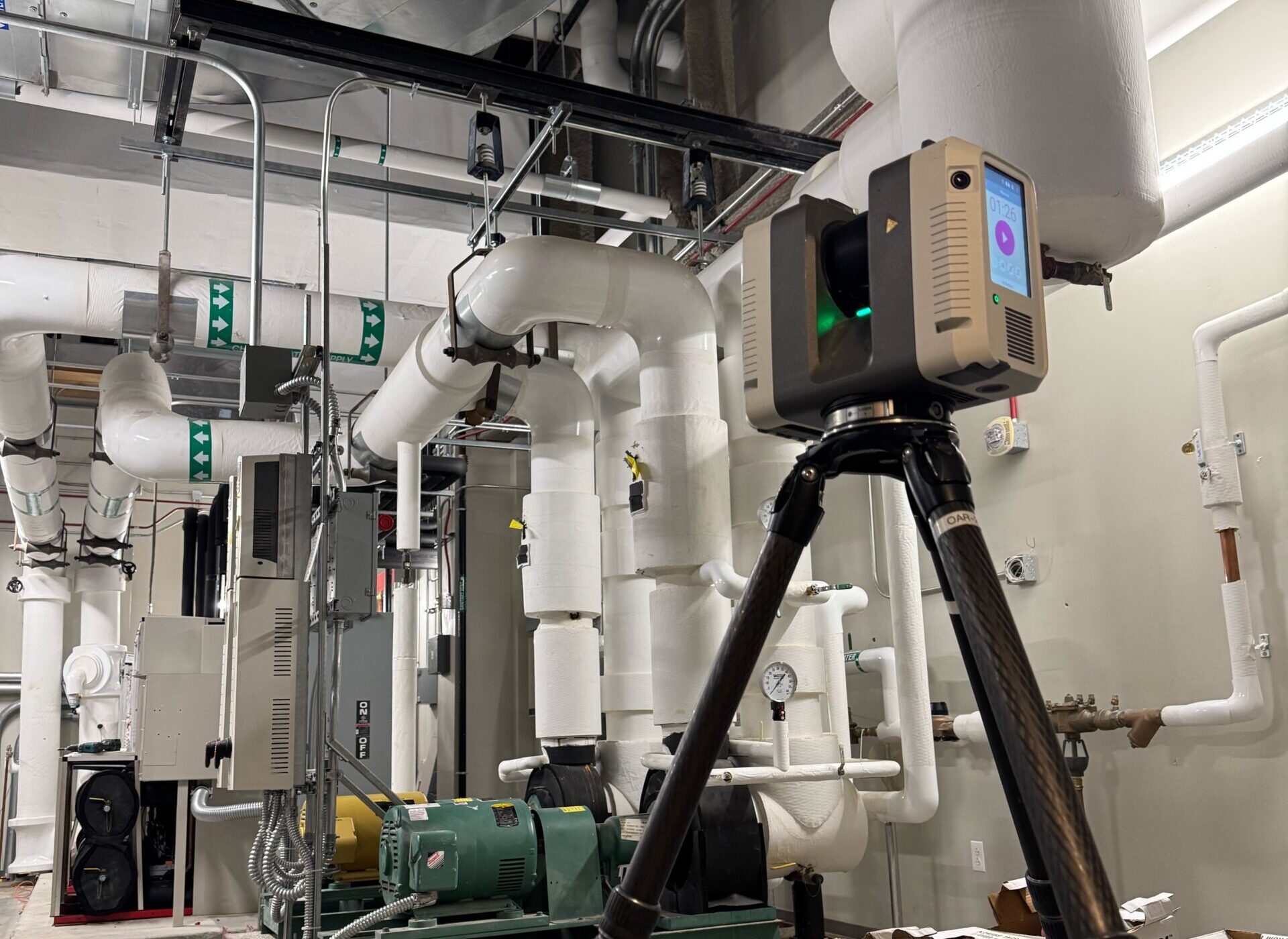
A laser scanner records millions of measured points per scan position, building a point cloud that reflects the actual geometry of the facility: piping runs, structural members, cable tray, ductwork, and equipment positions, all captured at millimeter-level accuracy. The scanner does not need physical access to every surface it measures, which matters in a plant where some areas are elevated, congested, or otherwise difficult and hazardous to reach by hand.
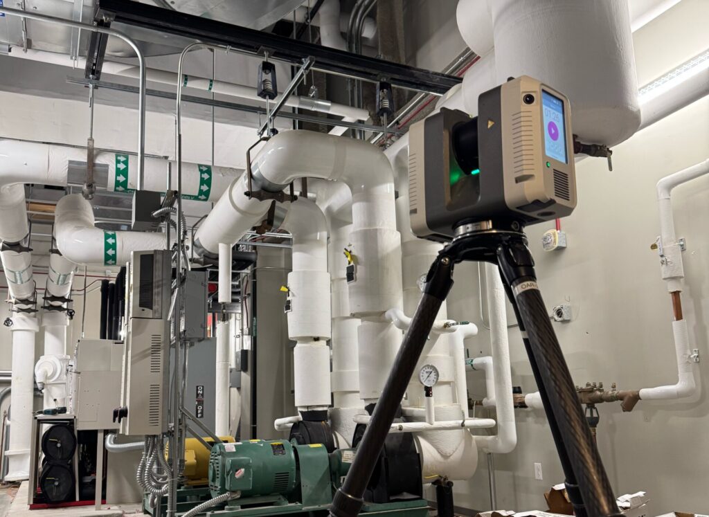
That point cloud becomes the basis for as-built drawings, a coordinated BIM model, or both, depending on what the project needs. Either way, the documentation reflects what is actually installed, measured directly, rather than an estimate built from drawings that may not have been updated since the facility’s original construction.
What Changes for the Project Team
When a scan-based existing conditions model is available before design begins, routing decisions can be checked against real geometry instead of assumed clearances. A tie-in point that looks clear on paper can be checked against the actual pipe rack, the actual conduit run, the actual structural member in that location. Conflicts that would otherwise surface mid-installation, when a crew is standing in front of the problem, can be identified and resolved on the model instead.
This does not remove every unknown from an industrial project. Facilities of this complexity will always have some conditions that surface only once work begins. What scanning changes is the starting point: the design and construction team is working from measured conditions for the majority of the plant, rather than treating the entire existing facility as an unknown to be discovered in the field.
Where This Applies Most Directly
Industrial laser scanning applies most directly to plant expansions, equipment replacements, process modifications, and retrofit projects in facilities that have been operating long enough for the built condition to diverge meaningfully from the drawings. MRF and recycling facility operators, manufacturing plants, and process industries tend to be the environments where this gap is widest, given the density of installed systems and the frequency of operational changes over a facility’s lifespan.
Teams planning an expansion or retrofit in a complex industrial facility and wanting to understand what scanned existing conditions would change in the design and coordination process can discuss the scope directly.
FAQs
What is industrial laser scanning?
Industrial laser scanning is the use of terrestrial LiDAR technology to capture the existing conditions of a plant or manufacturing facility, recording millions of measured data points that document piping, structural steel, electrical systems, cable tray, ductwork, and equipment positions at millimeter-level accuracy. The resulting point cloud can be used to produce as-built drawings, a coordinated BIM model, or both.
Why do industrial facility drawings often not match what is actually installed?
Industrial facilities change continuously through operational life: equipment gets replaced, piping gets rerouted during maintenance or shutdowns, and emergency repairs add components that may not be recorded in the drawing set. Original design drawings reflect the facility as it was built, not as it exists after years of undocumented modifications.
Where do the biggest documentation gaps occur in industrial plants?
The building shell is usually the most stable and accurately documented part of an industrial facility. The systems inside it, piping, electrical distribution, cable tray, and process equipment, are the parts most likely to have changed since the original drawings were produced, and they are also the systems a new project has to route around.
How does scanning change planning for a plant expansion or retrofit?
With a scan-based existing conditions model, routing decisions for new systems can be checked against measured geometry instead of assumptions drawn from outdated drawings. Conflicts between proposed work and actual existing conditions can be identified before construction begins, rather than discovered in the field once a crew starts work.